


Industrial Power
24V
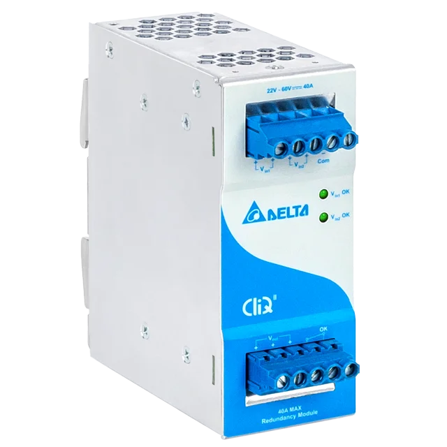
40A
22-60Vdc
121 x 50 x 122.1 mm
4.76” x 1.97” x 4.81”
0.52 kg (1.15 lb)
| Model | Description |
|---|---|
| DRR-40N | Without Class I, Div 2 and ATEX |
24V
40A
22-60Vdc
121 x 50 x 122.1 mm
4.76” x 1.97” x 4.81”
0.52 kg (1.15 lb)
| Model | Description |
|---|---|
| DRR-40N | Without Class I, Div 2 and ATEX |